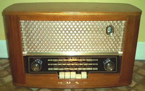
Bush VHF62
I have a bit of a soft spot for these 1950's "piano key" radios. Once sorted, they seem to perform pretty well, some of them exceptionally so.
This one is particularly attractive, having a light wood veneered cabinet instead of the more usual plastic. I spotted it at a BVWS auction and it looked in pretty good condition. Unfortunately, on closer inspection, some of the veneer along the top edge had been damaged. Luckily the manufacturer had continued the veneer all round the back, however, and so a "grafting" operation was possible! The real test of patience was removing the old damaged varnish without lifting the gilt coachline.
Previous experience of these receivers had led me to a false conclusion. Although I had been impressed with their lively AM performance, FM reception had always been disappointing. I had put this down to low gain in the front end and what I assumed was a normal amount of distortion from the valve ratio detector. On switching this one to FM however I was pleasantly surprised. Good sensitivity (two i.f. stages clearly make a difference) and quite reasonable quality. This is helped enormously by the provision of a magic eye - a really useful tuning aid in the absence of AFC.

I have now concluded that my previous bad experiences with valve VHF receivers had probably been due to loss of alignment and aged capacitors (the electrolytic in the ratio-detector is a good candidate for automatic replacement). When aligned and working properly they are capable of good results.
This radio has now taken its place in the dining room as the "meal time" receiver. Luckily, the FM local oscillator was slightly mis-aligned in the direction enabling Classic FM to be received (my teenage son doesn't agree with this sentiment, however!).
Sequel
Having used the radio for a while, I gradually became dissatisfied with the level of distortion on FM, most noticeable on music with sustained bass notes and also on heavy piano pieces. Furthermore, I noticed that the optimum tuning point did not quite coincide with the signal maximum as indicated by the magic eye. All this pointed to the need for re-alignment of the FM i.f. stages.
So it was out with the trusty signal generator and carefully filed plastic knitting needles!
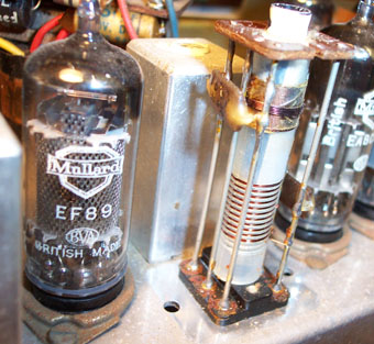
First problem was that the top core of the final i.f.t. wouldn't budge. The manufacturers had used the white locking compound that sets rock hard and even with a plastic tool, bits of the core were starting to break off. I tried the trick of removing the bottom core and accessing the lower slot but this didn't help. That end started to crack too. I tried various lubricants down the hole but to no avail (the core was in too deep to try a hot soldering iron). I was about to resort to the dreaded drill when I thought about solvents. The lockant appeared rather like paint (maybe it was!). I considered the use of "Nitromoors" but this seemed a bit extreme. Eventually I popped in a couple of drops of cellulose thinners. Within a few minutes the core was on the move and was carefully extracted. The hard locking compound had turned into a viscous goo which was easily removed (as were any remaining thinners in case the stuff started working on the plastic coil former!).
Carefully following Trader sheet 1301, everything peaked nicely until I got to that last i.f.t. Here the primary should be peaked at 10.7MHz and the secondary adjusted to the linear portion of the discriminator response curve (as described on Paul Stenning's website). But I couldn't get the primary to peak sensibly and its setting seemed to be strongly influenced by the position of the secondary core. After a lot of fiddling the truth began to dawn on me. The coils appeared to be reversed from the information in the Trader sheet. If I peaked the top core, the bottom one then display the classic "S" shape discriminator response. As I couldn't really believe such a fundamental error, I decided to take the can off to have a look. Sure enough - the split secondary (L22) was at the bottom and the primary with overwound tertiary coil (L21/L23) was at the top. Either "Trader" got it wrong or Bush changed to a different i.f.t. design for some reason (strictly sheet 1301 is for the VHF61 but I assumed the only difference in the VHF62 was the wooden cabinet).
Now the optimum tuning point was back at the point of maximum signal and the quality was much improved. As a final tweak I added a 27K damping resistor across the primary to flatten the response a bit - I guess they used less deviation back in the fifties!
The only other modification I made was to move the magic-eye target electrode to the top of the reservoir capacitor where the few extra volts make the fading phosphors just that little bit brighter - for a while!
Back to Radio Gallery