T1154 Transmitter
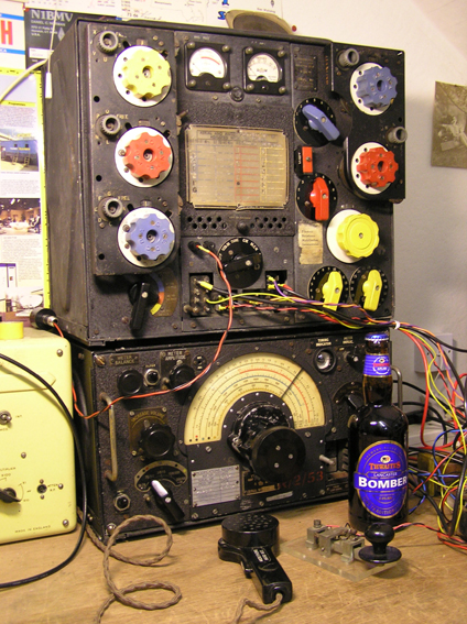
This is the famous Lancaster bomber
transmitter used during the latter part of WWII along with it's companion
R1155 receiver. Ever since hearing the evocative sound of one on the VMARS
80 metre net, I knew it was something I wanted to have in my collection. They
are, however, very collectable and the sort of prices they made on Ebay made me
doubt that I would ever realise my ambition. So when one came up as part of a
"silent key" sale at my local radio club, I decided to go for it. Although
it wasn't exactly "going for a song", it was just about affordable and I was
lucky enough to get it along with a couple of R1155's.
As can be seen from the "as received" pictures, it was in a bit of a state, having been stored in a damp garage for many years. Most of the "Lego" style controls were seized solid through corrosion and there were signs that it had had a bit of a hard life. The good news, though, was that it was original, not having been "got at" by the dreaded radio amateur modifier brigade (of which I was once a fully paid up member!). In the 50s and 60's, these sets could be bought, brand new in original packing crate, for around £10 from various surplus emporia in the Soho district of London. Tales are told of enthusiastic young lads staggering onto the tube under the weight of them. Many of them, of course, were bought only to be stripped down for spares. They were, after all, an excellent source of wide-spaced variable capacitors and high quality inductors, not to mention a rather nice RF ammeter. I would have probably done the same if I could have afforded the £10!
Many hours and half a can of WD40 later, all the mechanical parts were freed up and some of the rust removed. I even managed to create a replica of the horribly warped and shrunken front cover frequency chart using a computer drawing package. Set behind a sheet of thin perpspex, it should look OK. So now it was time to tackle the electronics. Internally the TX didn't look too bad. The cotton covered wiring was pretty much intact and most of the components looked in reasonable condition. In fact, there really aren't that many electronic components in there! Apart from the switching, the basic circuit is pretty simple. Triode VFO and a triode speech amplifier/MCW-oscillator modulating the suppressor grids of a parallel pair of pentode PA's. Basic 1930's technology, really, and all powered from 6V and 1200V!
Click on photo to enlarge

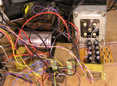
Both of the supplies were to prove a bit problematical. The 6V needed to be DC and well smoothed as the PT15 PA valves were directly heated and the keying relay was a DC type. I also wanted to run the receiver from this as well so over 8 amps would be required. I eventually settled on a low drop-out regulator circuit using a low resistance FET to reduce the dissipation to manageable levels. The 1200V supply was fairly straightforward as I had managed to obtain a suitable transformer from the same sale. This was a bit of a beast, however, with a 250mA rating. I would definitely have to keep one hand in my pocket during the testing phase! As can be seen, the initial lash up would not win any health and safety awards! I would make a proper job of it later, though. Honest!
The next problem was that I didn't yet have all the appropriate Jones connectors, especially the single contact one for the high voltage. So a little improvisation was called for. With a bit of judicious easing using a pair of pliers, a "Lucar" connector becomes a snug fit on the male spade pins of the Jones plugs, and a rolled tube of sheet Copper mated successfully with the 1200V pin. It wasn't pretty but it would do the job until the right connectors could be found.
To my great surprise, applying power and pressing the key was all that was required to bring this old transmitter back to life, at least on CW. I was getting 75W output on 80 metres with well over 25W in the R/T position. With the set configured for carbon microphone, an army hand mic. No.3 was connected and modulation could be heard. With a suitable source of voice lubrication fluid to hand, it was time to try it out on the air.

Sadly, initial reports were less than flattering: "Strong carrier but modulation low" and "Very thin sounding mod". Strange that - it sounded OK in the shack and even looked reasonable on a scope. It took a while for the penny to drop - I seemed to be getting rather too much power out in R/T and the mod wasn't right. After much head scratching I eventually looked at the suppressor grid voltage. It was quite a bit higher than it should be. The problem was, in fact, what vintage radio restorers refer to as "that capacitor"! The blocking capacitor (C8) between the anode of the speech amplifier and the PA suppressor grids was leaky, shifting the operating point. Result: more power but poor mod. Unfortunately, C8 turned out to be half of a large oil filled can bolted to the bottom of the chassis. So for the time being it was disconnected and a modern replacement tacked in (along with C21 which had suffered the same fate). Hopefully one day I'll find the correct replacement - or maybe I'll even re-stuff the original can. Even though it can't be seen from outside, it would be nice to keep the internals looking original. Suffice it to say that on-air reports were now fine. I did find, however, that the transmitter really needs to be "talked up", even to the point of apparent over-modulation. Presumably, the operator would have been shouting above the noise of the aircraft. Later on I did a SPICE model of the modulation circuit and discovered a steadily rising frequency response starting at about 800 cycles. I guess that is the characteristic "1154 sound".
The army "Microphone, Hand No. 3" is , of course, not the
correct kit for a Lancaster bomber. So, I started looking round for something a
bit more original. I eventually bought a rather rusty A1134A intercom amplifier
at a vintage exhibition and Ebay provided an original oxygen mask microphone.
That turned out to be the easy bit, however. It may surprise readers to know
that the intercom system in a
wartime Lancaster ran on dry batteries! An external 120 volt battery and 2volt
cell were used, with a 6 volt grid bias battery in the amplifier itself. So
another power supply had to be made. The next problem was that the A1134
microphone transformer had an open circuit secondary so quite a few hours were
spent rewinding thousands of turns of hair-thin wire using my trusty hand-drill
method. And, of course, Sod's law dictated that the microphone itself was also
dead on arrival. Luckily, the break in the winding was near the surface so all
it needed was a good magnifying glass and a steady hand. Eventually it all came
together and I have to say that it was worth all the effort to be able to
use that original line-up. I didn't go as far as bidding for an original oxygen
mask, although it would certainly have prevented excessively long overs!
Click here for short-form A1134 manual.
So there we are. You'll be relieved to know that I did rebuild the PSU so the 1200V is now safely inside an earthed enclosure. I also managed to find some suitable (although not original aircraft fit) Jones connectors. The whole station is now up and running and can be heard on 3615kHz when conditions are suitable.
Listen to audio clip of G3XGW on T1154
Download RAAF T1154/R1155 Technical Description - a rather nice document with user-friendly descriptions and simplified diagrams (16.7Mb)
Back to Air Force Radios