B-Set transplant

Although my previous restoration had, at least, resulted in something looking like an original 19 set, I was always conscious of the fact that a large chunk of it was still missing. Whenever the set was removed from its case, the empty space where the B-Set and Intercom amplifier used to reside was a nagging reminder of my boyhood butchery!
Initially, I had a go at rebuilding the I/C amplifier. This was not particularly difficult - it was, after all, just a two valve circuit using a 6K7 and a 6V6. I tried to base this on the REME modification performed on many sets at the time.

Unfortunately, I had to cheat somewhat by using some modern components and alternative transformers which rather spoilt the look of the thing. However, it did mean that I could now use the amplifier to boost the microphone level before applying it to the transmitter input using the same configuration as the No.10 control box (or "quiet box"). This was designed for use when the vehicle was stationary to avoid the operator having to shout into the microphone - probably not the best security practice!
At this stage I thought that this was about as far as I could go with the restoration project - the prospect of rebuilding the B-Set from scratch was just too daunting to contemplate.
What I hadn't taken into account, however, was the kindness of a fellow amateur and VMARS member from Birmingham. He must have heard me bemoaning the impossibility of further progress and, out of the blue, emailed to say that he had a donor set that I could use. It had, apparently, already been somewhat cannibalised, but he thought the B-set and I/C amplifier were still complete. I couldn't believe my luck but in short order the set had been collected and I was ready to start. By sheer fluke the set was a British Mk III and built by the same manufacturer as mine - E.K.Cole and Sons (aka Ekco).
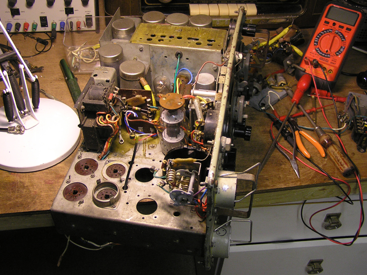
From the top, all the major components were still present and correct. Rather apprehensively I tested the transformer windings but all appeared to be intact. There would be some interesting times undoing those almost inaccessible nuts and bolts but it all looked possible, given the odd expletive!
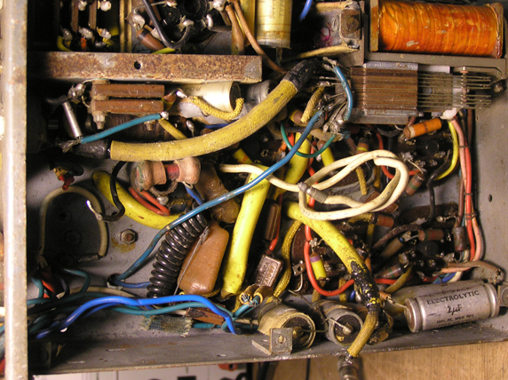
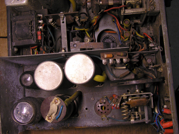
Under the chassis, however, was a rather different story. The prospect of de-soldering all those resistors and capacitors from the valve bases and re-assembling them in my chassis didn't bear thinking about. It took a while to dawn on me that this huge amount of work could be avoided by re-locating the whole lot in one go - valve bases and all. Swapping the B-Set and I/C Amplifier would be rather akin to performing a combined heart and lung transplant - albeit with rather less blood!
So this is how it was done. Lots of photographs were taken so that I could hopefully determine later how to re-connect the major arteries and eventually, the whole assembly was moved from one set to the other. A couple of capacitors were judged to be too leaky and were replaced with old stock of a similar vintage. On the whole, however, very little was changed. More care was taken over the I/C amplifier as that would be used in conjunction with the main transceiver. The B Set, however, once its correct operation had been established, would not be usable due to its frequency range not being part of the UK amateur allocation.

Considerable head scratching and consultation of "Wireless for the Warrior" was required to re-connect the wiring. One lesson I have learned is, however many photographs you take, it is never enough. There is always at least one wire that refuses to be identified as it dives under some obscuring component or other!
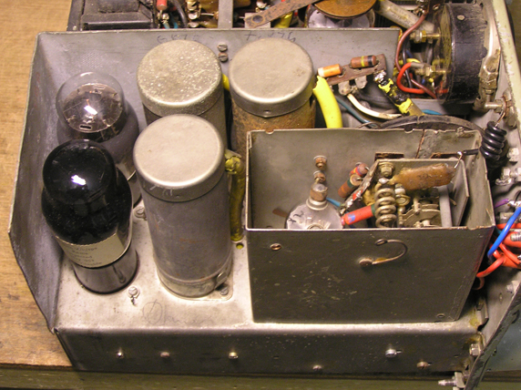
But in the end, it all came together. The valve skirts and screening cans were fitted and the VHF section screening can was bolted into place (shame that someone had taken a pair of tin snips to it at some time in its life) . Maybe one day I'll find a lid for it! (I did too!)

The connector and switches were rewired, the relay mounted. Eventually the destination of that last mystery wire was discovered.
.
Testing commenced very gingerly! At first only the 12 volts was applied. It was nice to see the appropriate heaters light up depending on the function selected. This did require a squirt of WD40 and vigorous exercise of one of the toggle switches, however. Then that second relay clacked across nicely when the appropriate connector pin was grounded. All OK so far - now for the exciting bit. With eyes and nose on full alert, HT was applied and I'm happy to report that there was no leakage of magic smoke! The I/C amp was tried first and with a 50/50 chance of getting the feedback the right way round...I'd created an oscillator! However this was easily sorted and resulted in a seriously loud intercom output. Next, the headphones were connected to the B set output. I didn't really know what to expect from a super-regenerative VHF receiver. How would I know if it was working? I needn't have worried. The amount of hiss told me that something was definitely squegging nicely, a quick look with a scope showing bursts of something very fast at 10uS intervals. With a test lead on the aerial socket I could even hear some sort of data signal at one end of the band. Briefly toggling the relay produced a reasonable amount of RF which appeared to modulate when I yelled into the microphone. So it was all basically working. Any further testing will have to wait till I fix my Eddystone 770U.
So there we are. It's a great feeling that the beast is finally fully brought back to life. I feel that the sins of my youth are expunged at last! Thanks Ron.
