
19 Set - The Early Years
My interest in military radio started early. Whilst still a schoolboy, I would scour the back pages of "Cam's Comic" (the somewhat derogatory nickname for "Practical Wireless") drooling over all the goodies on offer. It was there in abundance! Numerous emporia would regularly advertise surplus equipment of all types from night vision goggles to air raid sirens. In amongst these was ex-forces radio equipment at give-away prices (well saved-up pocket money prices at least). From famous receivers such as the Lancaster's R1155 and the RCA AR88 right through to transceivers such as 38 sets and the ubiquitous No. 19 set. They must have bought these by the truck load!
Click on image for full advert
It was the latter that attracted my interest. I can just about
remember the wording of the advert (from somewhere in Lisle Street or Tottenham
Court Road). "2-8 Mc/s transmitter-receiver, complete with 12 foot whip aerial"
And the price…79/6d (that might even have included carriage!) I was enthralled at the thought of having my own transmitter.
I would picture myself there, microphone in hand, talking to people all over the
world (licence - what licence?). And it was so cheap - I could save up for it
in……well, not too long. Perhaps a parental birthday/Christmas contribution would
speed things up. So I pestered Mum and Dad, explaining what a bargain it was and
how badly I wanted it. Eventually I wore them down (probably promising to always
do my piano practice as soon as I got in from school - I'm sure you all remember
the tricks). Eventually the postal order was sent off and the waiting began -
expectant face through the door every evening - only to be disappointed time
after time. But then - the great day! A large parcel awaited me on my return
from school (what! - piano practice? - I'll do it later, honest). Now for the sad bit! What I hadn't considered in all my
excitement were the electrical arrangements in the standard British WW2 battle
tank (this of course being the previous home of the 19 set). I think I naively
believed that this wondrous piece of equipment would come with a mains lead to
which I would merely have to fit a 13 amp plug and off it would go. Oh dear!
When the box was eventually opened, there was a rather battered looking set,
covered in grime, with two totally incomprehensible 12 pin connectors for
connections to the outside world (I suppose the power supply was extra!). I
sadly realised that I wasn't going to be on the air tonight or for a good many
nights to come and now understood the small print at the bottom of the advert
stating "modification leaflet included"! The box was duly packed up again with
consoling words like "perhaps when you're a bit older". Tears on the pillow, I
shouldn't wonder.
As my knowledge increased, however, more of the circuitry started to make sense. I eventually deduced that the heater chain and relays required 12 volts d.c. (normally supplied by the tank's battery, of course). Unfortunately we didn't run to a family car in those days. But I did have a model railway and that worked off 12 volts. I was fairly sure I'd figured out which pins to connect it to so I gave it a go (I think I soldered wires direct to the pins!). Hey presto - the LT meter flicked up to 11v and slowly but surely all the valves started to glow (I ignored the protestations from the somewhat overloaded transformer). This was a major step forward - the set was coming to life.
The next step was to find an HT supply for the receiver. The circuit seemed to indicate that around 275 volts was required. By now I had a collection of domestic valve radios in various states of repair/disassembly. Maybe the power supply section from one of these could be pressed into service. More wires were soldered to the 12-pin connector, strung across to an upturned set. A pair of ancient headphones was connected and an aerial lead somehow attached to the inner of the big "A" set aerial connector. Fingers were crossed and power was gingerly applied. To my utter amazement, even before I'd put the headphones on, a tremendous racket could be heard. I think the set must have been left tuned somewhere around 6 MHz and where the usual nightly battle between Radio Moscow and some teleprinter or other was going on.
Late into the night I listened in wonder - the sensitivity was incredible compared with the cloth-eared domestic short wave sets. I must have tuned up and down between 2 and 8 MHz until my ears were nearly dropping off from the uncompromising ebonite of the headphones. And then I discovered the BFO - you could get some really amazing sounds using that!
Eventually, just listening wasn't enough. There was that big chunky 807 doing nothing except consuming heater power. Sacrilege really! But getting the TX going was a bit more of a challenge. There was the little matter of obtaining a 550 volt supply. I had the idea of using a 300v-0-300v transformer with the two halves of the secondary in series followed by a half wave valve rectifier with strings of series capacitors for smoothing. This was duly constructed on a hardboard and batten chassis, would you believe. Talk about lethal! What I'd forgotten was that the 300v was RMS. On first switch on, as the rectifier heaters warmed up, the off-load voltage soared up to about 900 volts. I hastily pulled the plug!
Eventually I got something approaching the right voltage - now it was time for the big test. Poring over the circuit again I found that the changeover relay coils went to a pin labelled "pressel switch". I had no idea what a "pressel switch" was but reckoned that grounding this pin should do the trick. The ubiquitous crocodile clip was nervously touched onto the pin. The almighty "clunk" as the relays went over nearly made me jump out of my skin! Then everything went deathly quiet and realisation dawned that I was "on the air"! I hurriedly switched back to receive!
The next step was to get some modulation. Trouble was, I didn't have the necessary electomagnetic microphone - only a crystal mic from my tape recorder. Out came the hardboard and battens again resulting in a neat little valve microphone pre-amplifier (EF86 I think it was). I think I wired it via the internal microphone transformer so it must have been a bit of a mis-match. But it worked! There was my voice coming out of the domestic set on about 6.5MHz.
I'd better gloss over the next few months - for fear of self-incrimination! Suffice it to say that I persuaded two of my school mates to follow my lead and some interesting contacts were to be heard on various frequencies with call-signs that were suspiciously reminiscent of the initials of teachers at the local secondary-modern!
Eventually, however, everything was made legal by the acquisition of an amateur call-sign and the much-modified 19 set made many contacts on 80m and 40m. It was even pressed into service by the radio club at the local grammar school - still with its wooden power supply!
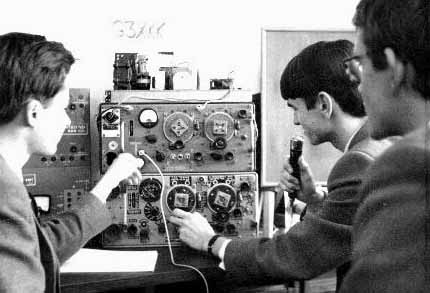
G3XKK - Poole Grammar School Radio Club