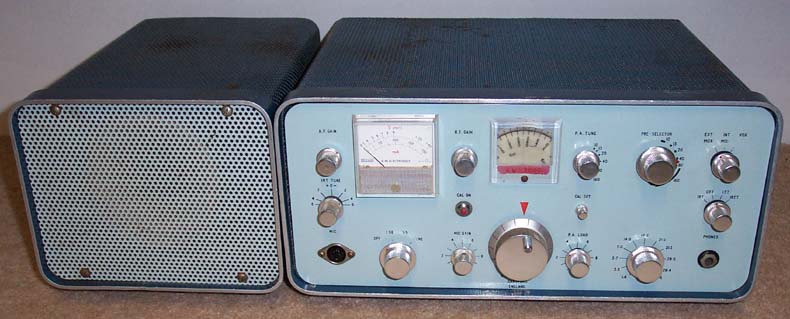
KW2000 Transceiver
I've been using this rig since I bought it in 1974. Even then, it wasn’t exactly in it's first flush of youth. It was purchased second-hand from an amateur in Birmingham for £100 having been spotted in an advert in the "Radcomm" (the RSGB Bulletin as was).
This was my first venture into the exotic world of single-sideband (until then I had been a die-hard AM man). It has had a fair bit of use over the years and has been remarkably reliable (considering that its all valve and full of horrible Hunts capacitors).
Its performance is not brilliant by today's standards. The receiver lacks sensitivity on the HF bands and the transmitter PA has to be tuned manually so at least three hands are required. Also, the VFO drifts slightly with the mains voltage (although that can be improved if you’re prepared to suffer the indignity of a solid state regulator for the VFO heater!). Of course it doesn’t have all the bells and whistles of a modern transceiver, although this is often not a great loss! Knowledge of the operating frequency to 6 decimal places or the ability to adjust the audio response using a DSP spectrum analyser isn’t what amateur radio should be about in my view!
For it’s day it did have some quite advanced features, however. VOX (voice operated transmit) and independent RX and TX tuning capability were pretty innovative at the time.
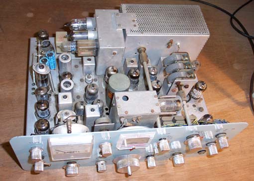
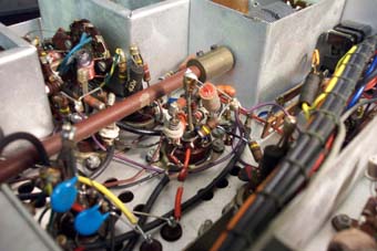
The advantage of this sort of kit is that you can get in there and fix it when it goes wrong. It uses components that can actually be seen without the aid of a microscope! The method of under-chassis construction does give rise to some controversy, however. Components are suspended between the valve-base pins and vertical wire "stakes" soldered into in the centre spigot. Parts requiring to be joined are inserted into wire coils which are then filled with solder. You either like it or hate it. Personally I don’t have a problem with it (at least it makes replacement of the horrible Hunts capacitors relatively painless!)
|
|
|
|
Valve-base "stake" construction |
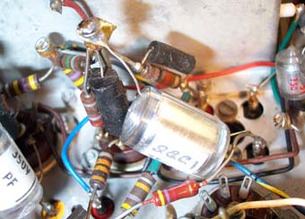
Detail of "stake" with black horrible Hunts capacitors |
One rather annoying feature is the choice of incrementally tuned circuits. i.e. the HF coils are in series, the tapping point being selected by the band switch. This means that if you adjust a coil on one band……yep, you guessed it!
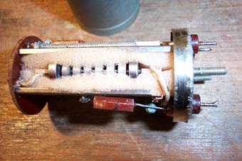
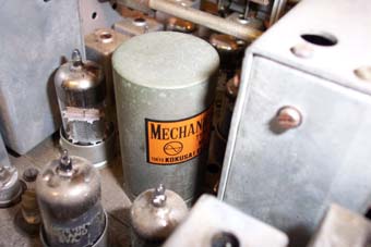
The outstanding feature of the rig in its heyday was the amazing Kokusai mechanical filter. I took this for granted for years until one day it suddenly died. I vaguely remembered hearing a story about this eventuality – it had something to do with foam! Anyway, not being one to give up at the first hurdle (the filters are, needless to say, obsolete) I decided to investigate further. By de-soldering the can seal, the contents can be extracted for inspection.
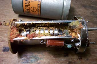
Now there are diagrams of this device in the RSGB handbook, but they don’t really prepare you for the reality of the situation. Personally, I find it hard to get my head round the fact that you can feed a half MHz signal into a piezo-electric device at one end, pass the resulting vibrations down a resonant steel structure (allegedly hand tuned by Japanese girls wielding tiny files) and recover the signal using another piezo device at the other end. However, it really works - and gives an excellent shape factor to boot! The only problem is that the ingenious Japanese manufacturers obviously didn’t envisage the longevity of the end equipment. They supported the otherwise rather fragile filter assembly in urethane foam. In the course of the next 30 years, this foam disintegrated into a sort of gooey orange powder that singularly fails in its primary function i.e. supporting! The next time the rig is up-ended (e.g. to replace one of the horrible……yep, you’ve got it), the filter assembly plummets to the end of the can, snapping the delicate wires to the piezo crystal, and it’s a gonner.
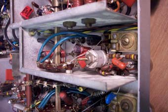
However, in the words of the classic TV series, "we have the technology – we can rebuild it". All you need is patience and a (very) steady hand. It’s simply a case of removing the orange goo (nail varnish remover works quite well), replacing the thin wires (soldering to the piezo-crystal metallisation is a bit tricky), wrapping the whole thing in some new foam and gently easing it back into its frame. Back on with the can and you’re back in business.
 |
|
|
Can removed revealing orange "goo" |
Filter re-assembled |
I suspect that the insertion loss has gone up a couple of dBs on what it was – not sure how much damping the foam produces (lets face it there can’t be much mechanical displacement at 455kHz)! Possibly the transformers at each end need tweaking but I don’t have a wobbulator so I didn’t mess with them. The good news is the rig’s back on the air and apparently sounding fine.
The only other real problem area with this example is neutralisation of the PA on the HF bands. I don't think that the 6146 in there is the original and I've heard somewhere that the valve manufacturer is a bit critical in this regard. I've used the transmitter successfully on the 20 and 15 metre bands but 10m has never quite tuned up properly. Presently, I'm getting self-oscillation on all the HF bands so maybe another of the horrible H...s capacitors has given up the ghost. I shall have to investigate.
One of the more recent disasters was the destruction of the TX power supply. I only use the rig sporadically so I suppose leaving it switched on whilst going to lunch one day was a bit foolhardy! I returned to a dead transceiver and the acrid stench of ex-transformer. The bench area was stained brown all around the rig leaving a "crime scene" type outline! I think the wax smoke must have drifted downwards as the ceiling mounted smoke detector hadn't uttered a single beep. It turned out that one of the snubber capacitors included to remove the commutation spikes from the rather ancient HV diodes had gone short circuit. Unfortunately, the series resistor was just too high to cause the fuse to blow but low enough to seriously overload the transformer which is now a blackened ruin. Until I can get another transformer I'm running the TX using a voltage doubler arrangement straight off the mains. As long as I remember it's not isolated, things will be OK (don't try this at home, folks!).
So, hopefully there are many more years of operating left in the old rig. Transistors - who needs 'em!
Back to Old Radios